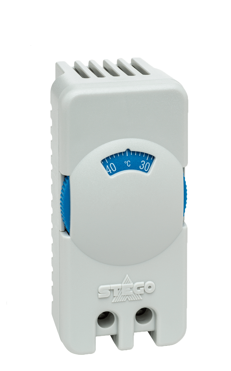
Thermostat switch (NO)
STS 011
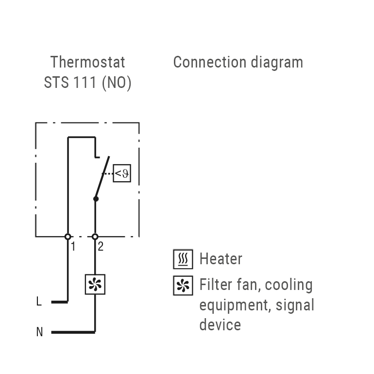
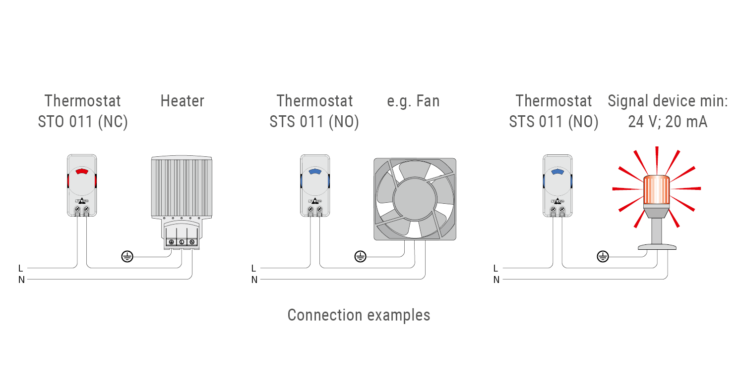
The mechanical thermostat NO (normally open) closes when the temperature rises and is used to control filter fans, heat exchangers, cooling devices or to switch signal transmitters when the temperature is exceeded. The bimetal thermostat has a small hysteresis.
- Thumbwheel setting dial
- Small hysteresis enables precise control
- Optimized air inlets
- High switching capacity